本文基于vscode+PlatformIO
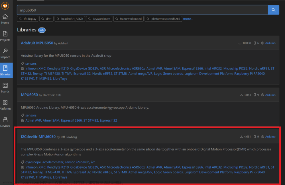
使用库:
接线:
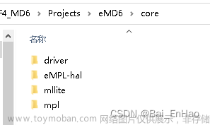
Arduino ESP32 I2C管脚定义:Arduino.h(第209行左右) -> pins_arduino.h如图:

VCC---3.3v
GND--GND
使用&&测试例程:
简单使用()
代码位置

代码如下(直接粘的):
// I2C device class (I2Cdev) demonstration Arduino sketch for MPU6050 class
// 10/7/2011 by Jeff Rowberg <jeff@rowberg.net>
// Updates should (hopefully) always be available at https://github.com/jrowberg/i2cdevlib
//
// Changelog:
//      2013-05-08 - added multiple output formats
//                 - added seamless Fastwire support
//      2011-10-07 - initial release

/* ============================================
I2Cdev device library code is placed under the MIT license
Copyright (c) 2011 Jeff Rowberg

Permission is hereby granted, free of charge, to any person obtaining a copy
of this software and associated documentation files (the "Software"), to deal
in the Software without restriction, including without limitation the rights
to use, copy, modify, merge, publish, distribute, sublicense, and/or sell
copies of the Software, and to permit persons to whom the Software is
furnished to do so, subject to the following conditions:

The above copyright notice and this permission notice shall be included in
all copies or substantial portions of the Software.

THE SOFTWARE IS PROVIDED "AS IS", WITHOUT WARRANTY OF ANY KIND, EXPRESS OR
IMPLIED, INCLUDING BUT NOT LIMITED TO THE WARRANTIES OF MERCHANTABILITY,
FITNESS FOR A PARTICULAR PURPOSE AND NONINFRINGEMENT. IN NO EVENT SHALL THE
AUTHORS OR COPYRIGHT HOLDERS BE LIABLE FOR ANY CLAIM, DAMAGES OR OTHER
LIABILITY, WHETHER IN AN ACTION OF CONTRACT, TORT OR OTHERWISE, ARISING FROM,
OUT OF OR IN CONNECTION WITH THE SOFTWARE OR THE USE OR OTHER DEALINGS IN
THE SOFTWARE.
===============================================
*/

// I2Cdev and MPU6050 must be installed as libraries, or else the .cpp/.h files
// for both classes must be in the include path of your project
#include "I2Cdev.h"
#include "MPU6050.h"

// Arduino Wire library is required if I2Cdev I2CDEV_ARDUINO_WIRE implementation
// is used in I2Cdev.h
#if I2CDEV_IMPLEMENTATION == I2CDEV_ARDUINO_WIRE
    #include "Wire.h"
#endif

// class default I2C address is 0x68
// specific I2C addresses may be passed as a parameter here
// AD0 low = 0x68 (default for InvenSense evaluation board)
// AD0 high = 0x69
MPU6050 accelgyro;
//MPU6050 accelgyro(0x69); // <-- use for AD0 high
//MPU6050 accelgyro(0x68, &Wire1); // <-- use for AD0 low, but 2nd Wire (TWI/I2C) object

int16_t ax, ay, az;
int16_t gx, gy, gz;


// uncomment "OUTPUT_READABLE_ACCELGYRO" if you want to see a tab-separated
// list of the accel X/Y/Z and then gyro X/Y/Z values in decimal. Easy to read,
// not so easy to parse, and slow(er) over UART.
#define OUTPUT_READABLE_ACCELGYRO

// uncomment "OUTPUT_BINARY_ACCELGYRO" to send all 6 axes of data as 16-bit
// binary, one right after the other. This is very fast (as fast as possible
// without compression or data loss), and easy to parse, but impossible to read
// for a human.
//#define OUTPUT_BINARY_ACCELGYRO


#define LED_PIN 13
bool blinkState = false;

void setup() {
    // join I2C bus (I2Cdev library doesn't do this automatically)
    #if I2CDEV_IMPLEMENTATION == I2CDEV_ARDUINO_WIRE
        Wire.begin();
    #elif I2CDEV_IMPLEMENTATION == I2CDEV_BUILTIN_FASTWIRE
        Fastwire::setup(400, true);
    #endif

    // initialize serial communication
    // (38400 chosen because it works as well at 8MHz as it does at 16MHz, but
    // it's really up to you depending on your project)
    Serial.begin(115200);

    // initialize device
    Serial.println("Initializing I2C devices...");
    accelgyro.initialize();

    // verify connection
    Serial.println("Testing device connections...");
    Serial.println(accelgyro.testConnection() ? "MPU6050 connection successful" : "MPU6050 connection failed");

    // use the code below to change accel/gyro offset values
    /*
    Serial.println("Updating internal sensor offsets...");
    // -76    -2359    1688    0    0    0
    Serial.print(accelgyro.getXAccelOffset()); Serial.print("\t"); // -76
    Serial.print(accelgyro.getYAccelOffset()); Serial.print("\t"); // -2359
    Serial.print(accelgyro.getZAccelOffset()); Serial.print("\t"); // 1688
    Serial.print(accelgyro.getXGyroOffset()); Serial.print("\t"); // 0
    Serial.print(accelgyro.getYGyroOffset()); Serial.print("\t"); // 0
    Serial.print(accelgyro.getZGyroOffset()); Serial.print("\t"); // 0
    Serial.print("\n");
    accelgyro.setXGyroOffset(220);
    accelgyro.setYGyroOffset(76);
    accelgyro.setZGyroOffset(-85);
    Serial.print(accelgyro.getXAccelOffset()); Serial.print("\t"); // -76
    Serial.print(accelgyro.getYAccelOffset()); Serial.print("\t"); // -2359
    Serial.print(accelgyro.getZAccelOffset()); Serial.print("\t"); // 1688
    Serial.print(accelgyro.getXGyroOffset()); Serial.print("\t"); // 0
    Serial.print(accelgyro.getYGyroOffset()); Serial.print("\t"); // 0
    Serial.print(accelgyro.getZGyroOffset()); Serial.print("\t"); // 0
    Serial.print("\n");
    */

    // configure Arduino LED pin for output
    pinMode(LED_PIN, OUTPUT);
}

void loop() {
    // read raw accel/gyro measurements from device
    accelgyro.getMotion6(&ax, &ay, &az, &gx, &gy, &gz);

    // these methods (and a few others) are also available
    //accelgyro.getAcceleration(&ax, &ay, &az);
    //accelgyro.getRotation(&gx, &gy, &gz);

    #ifdef OUTPUT_READABLE_ACCELGYRO
        // display tab-separated accel/gyro x/y/z values
        Serial.print("a/g:\t");
        Serial.print(ax); Serial.print("\t");
        Serial.print(ay); Serial.print("\t");
        Serial.print(az); Serial.print("\t");
        Serial.print(gx); Serial.print("\t");
        Serial.print(gy); Serial.print("\t");
        Serial.println(gz);
    #endif

    #ifdef OUTPUT_BINARY_ACCELGYRO
        Serial.write((uint8_t)(ax >> 8)); Serial.write((uint8_t)(ax & 0xFF));
        Serial.write((uint8_t)(ay >> 8)); Serial.write((uint8_t)(ay & 0xFF));
        Serial.write((uint8_t)(az >> 8)); Serial.write((uint8_t)(az & 0xFF));
        Serial.write((uint8_t)(gx >> 8)); Serial.write((uint8_t)(gx & 0xFF));
        Serial.write((uint8_t)(gy >> 8)); Serial.write((uint8_t)(gy & 0xFF));
        Serial.write((uint8_t)(gz >> 8)); Serial.write((uint8_t)(gz & 0xFF));
    #endif

    // blink LED to indicate activity
    blinkState = !blinkState;
    digitalWrite(LED_PIN, blinkState);
    delay(100);
}
上传,然后卡在初始化

原因:
可能是I2Cdev库和MPU6050库不同步(I2Cdev太新了)
解决:
依次检查 (F12)
main.cpp的accelgyro.initialize();==>
MPU6050.cpp的setClockSource(...);=>I2Cdev::writeBits(...);==>
I2Cdev.cpp的readByte(...)=>readBytes(...),可以确定
程序卡在 I2Cdev.cpp 的函数
int8_t I2Cdev::readBytes(uint8_t devAddr, uint8_t regAddr, uint8_t length, uint8_t *data, uint16_t timeout, void *wireObj)中的
 useWire->endTransmission();
 useWire->beginTransmission(devAddr);
上(大概第305行左右),解决方案就是把第二行注释掉
useWire->endTransmission(true);
// useWire->beginTransmission(devAddr);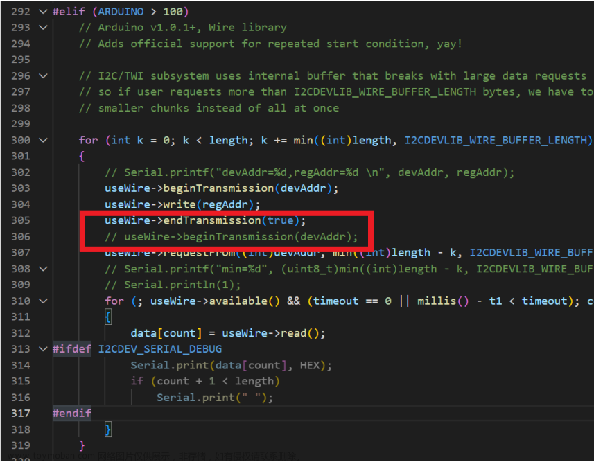
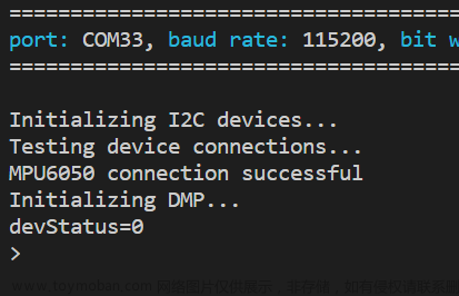
再上传:

问题解决
DMP使用
代码位置

代码(也是直接粘的)
// I2C device class (I2Cdev) demonstration Arduino sketch for MPU6050 class using DMP (MotionApps v2.0)
// 6/21/2012 by Jeff Rowberg <jeff@rowberg.net>
// Updates should (hopefully) always be available at https://github.com/jrowberg/i2cdevlib
//
// Changelog:
//      2019-07-08 - Added Auto Calibration and offset generator
//           - and altered FIFO retrieval sequence to avoid using blocking code
//      2016-04-18 - Eliminated a potential infinite loop
//      2013-05-08 - added seamless Fastwire support
//                 - added note about gyro calibration
//      2012-06-21 - added note about Arduino 1.0.1 + Leonardo compatibility error
//      2012-06-20 - improved FIFO overflow handling and simplified read process
//      2012-06-19 - completely rearranged DMP initialization code and simplification
//      2012-06-13 - pull gyro and accel data from FIFO packet instead of reading directly
//      2012-06-09 - fix broken FIFO read sequence and change interrupt detection to RISING
//      2012-06-05 - add gravity-compensated initial reference frame acceleration output
//                 - add 3D math helper file to DMP6 example sketch
//                 - add Euler output and Yaw/Pitch/Roll output formats
//      2012-06-04 - remove accel offset clearing for better results (thanks Sungon Lee)
//      2012-06-01 - fixed gyro sensitivity to be 2000 deg/sec instead of 250
//      2012-05-30 - basic DMP initialization working

/* ============================================
I2Cdev device library code is placed under the MIT license
Copyright (c) 2012 Jeff Rowberg

Permission is hereby granted, free of charge, to any person obtaining a copy
of this software and associated documentation files (the "Software"), to deal
in the Software without restriction, including without limitation the rights
to use, copy, modify, merge, publish, distribute, sublicense, and/or sell
copies of the Software, and to permit persons to whom the Software is
furnished to do so, subject to the following conditions:

The above copyright notice and this permission notice shall be included in
all copies or substantial portions of the Software.

THE SOFTWARE IS PROVIDED "AS IS", WITHOUT WARRANTY OF ANY KIND, EXPRESS OR
IMPLIED, INCLUDING BUT NOT LIMITED TO THE WARRANTIES OF MERCHANTABILITY,
FITNESS FOR A PARTICULAR PURPOSE AND NONINFRINGEMENT. IN NO EVENT SHALL THE
AUTHORS OR COPYRIGHT HOLDERS BE LIABLE FOR ANY CLAIM, DAMAGES OR OTHER
LIABILITY, WHETHER IN AN ACTION OF CONTRACT, TORT OR OTHERWISE, ARISING FROM,
OUT OF OR IN CONNECTION WITH THE SOFTWARE OR THE USE OR OTHER DEALINGS IN
THE SOFTWARE.
===============================================
*/

// I2Cdev and MPU6050 must be installed as libraries, or else the .cpp/.h files
// for both classes must be in the include path of your project
#include "I2Cdev.h"

#include "MPU6050_6Axis_MotionApps20.h"
// #include "MPU6050.h" // not necessary if using MotionApps include file

// Arduino Wire library is required if I2Cdev I2CDEV_ARDUINO_WIRE implementation
// is used in I2Cdev.h
#if I2CDEV_IMPLEMENTATION == I2CDEV_ARDUINO_WIRE
#include "Wire.h"
#endif

// class default I2C address is 0x68
// specific I2C addresses may be passed as a parameter here
// AD0 low = 0x68 (default for SparkFun breakout and InvenSense evaluation board)
// AD0 high = 0x69
MPU6050 mpu;
// MPU6050 mpu(0x69); // <-- use for AD0 high

/* =========================================================================
   NOTE: In addition to connection 3.3v, GND, SDA, and SCL, this sketch
   depends on the MPU-6050's INT pin being connected to the Arduino's
   external interrupt #0 pin. On the Arduino Uno and Mega 2560, this is
   digital I/O pin 2.
 * ========================================================================= */

/* =========================================================================
   NOTE: Arduino v1.0.1 with the Leonardo board generates a compile error
   when using Serial.write(buf, len). The Teapot output uses this method.
   The solution requires a modification to the Arduino USBAPI.h file, which
   is fortunately simple, but annoying. This will be fixed in the next IDE
   release. For more info, see these links:

   http://arduino.cc/forum/index.php/topic,109987.0.html
   http://code.google.com/p/arduino/issues/detail?id=958
 * ========================================================================= */

// uncomment "OUTPUT_READABLE_QUATERNION" if you want to see the actual
// quaternion components in a [w, x, y, z] format (not best for parsing
// on a remote host such as Processing or something though)
// #define OUTPUT_READABLE_QUATERNION

// uncomment "OUTPUT_READABLE_EULER" if you want to see Euler angles
// (in degrees) calculated from the quaternions coming from the FIFO.
// Note that Euler angles suffer from gimbal lock (for more info, see
// http://en.wikipedia.org/wiki/Gimbal_lock)
// #define OUTPUT_READABLE_EULER

// uncomment "OUTPUT_READABLE_YAWPITCHROLL" if you want to see the yaw/
// pitch/roll angles (in degrees) calculated from the quaternions coming
// from the FIFO. Note this also requires gravity vector calculations.
// Also note that yaw/pitch/roll angles suffer from gimbal lock (for
// more info, see: http://en.wikipedia.org/wiki/Gimbal_lock)
#define OUTPUT_READABLE_YAWPITCHROLL

// uncomment "OUTPUT_READABLE_REALACCEL" if you want to see acceleration
// components with gravity removed. This acceleration reference frame is
// not compensated for orientation, so +X is always +X according to the
// sensor, just without the effects of gravity. If you want acceleration
// compensated for orientation, us OUTPUT_READABLE_WORLDACCEL instead.
// #define OUTPUT_READABLE_REALACCEL

// uncomment "OUTPUT_READABLE_WORLDACCEL" if you want to see acceleration
// components with gravity removed and adjusted for the world frame of
// reference (yaw is relative to initial orientation, since no magnetometer
// is present in this case). Could be quite handy in some cases.
// #define OUTPUT_READABLE_WORLDACCEL

// uncomment "OUTPUT_TEAPOT" if you want output that matches the
// format used for the InvenSense teapot demo
// #define OUTPUT_TEAPOT

#define INTERRUPT_PIN 15 // use pin 2 on Arduino Uno & most boards
#define LED_PIN 2        // (Arduino is 13, Teensy is 11, Teensy++ is 6)
bool blinkState = false;

// MPU control/status vars
bool dmpReady = false;  // set true if DMP init was successful
uint8_t mpuIntStatus;   // holds actual interrupt status byte from MPU
uint8_t devStatus;      // return status after each device operation (0 = success, !0 = error)
uint16_t packetSize;    // expected DMP packet size (default is 42 bytes)
uint16_t fifoCount;     // count of all bytes currently in FIFO
uint8_t fifoBuffer[64]; // FIFO storage buffer

// orientation/motion vars
Quaternion q;        // [w, x, y, z]         quaternion container
VectorInt16 aa;      // [x, y, z]            accel sensor measurements
VectorInt16 aaReal;  // [x, y, z]            gravity-free accel sensor measurements
VectorInt16 aaWorld; // [x, y, z]            world-frame accel sensor measurements
VectorFloat gravity; // [x, y, z]            gravity vector
float euler[3];      // [psi, theta, phi]    Euler angle container
float ypr[3];        // [yaw, pitch, roll]   yaw/pitch/roll container and gravity vector

// packet structure for InvenSense teapot demo
uint8_t teapotPacket[14] = {'$', 0x02, 0, 0, 0, 0, 0, 0, 0, 0, 0x00, 0x00, '\r', '\n'};

// ================================================================
// ===               INTERRUPT DETECTION ROUTINE                ===
// ================================================================

volatile bool mpuInterrupt = false; // indicates whether MPU interrupt pin has gone high
ICACHE_RAM_ATTR void dmpDataReady()
{
    mpuInterrupt = true;
}

// ================================================================
// ===                      INITIAL SETUP                       ===
// ================================================================

void setup()
{
// join I2C bus (I2Cdev library doesn't do this automatically)
#if I2CDEV_IMPLEMENTATION == I2CDEV_ARDUINO_WIRE
    Wire.begin();
    Wire.setClock(400000); // 400kHz I2C clock. Comment this line if having compilation difficulties
#elif I2CDEV_IMPLEMENTATION == I2CDEV_BUILTIN_FASTWIRE
    Fastwire::setup(400, true);
#endif

    // initialize serial communication
    // (115200 chosen because it is required for Teapot Demo output, but it's
    // really up to you depending on your project)
    Serial.begin(115200);
    while (!Serial)
        ; // wait for Leonardo enumeration, others continue immediately

    // NOTE: 8MHz or slower host processors, like the Teensy @ 3.3V or Arduino
    // Pro Mini running at 3.3V, cannot handle this baud rate reliably due to
    // the baud timing being too misaligned with processor ticks. You must use
    // 38400 or slower in these cases, or use some kind of external separate
    // crystal solution for the UART timer.

    // initialize device
    Serial.println(F("Initializing I2C devices..."));
    mpu.initialize();
    pinMode(INTERRUPT_PIN, INPUT);

    // verify connection
    Serial.println(F("Testing device connections..."));
    Serial.println(mpu.testConnection() ? F("MPU6050 connection successful") : F("MPU6050 connection failed"));

    // wait for ready
    // Serial.println(F("\nSend any character to begin DMP programming and demo: "));
    // while (Serial.available() && Serial.read()); // empty buffer
    // while (!Serial.available());                 // wait for data
    // while (Serial.available() && Serial.read()); // empty buffer again

    // load and configure the DMP
    Serial.println(F("Initializing DMP..."));
    devStatus = mpu.dmpInitialize();
    // supply your own gyro offsets here, scaled for min sensitivity
    mpu.setXGyroOffset(220);
    mpu.setYGyroOffset(76);
    mpu.setZGyroOffset(-85);
    mpu.setZAccelOffset(1788); // 1688 factory default for my test chip
    Serial.printf("devStatus=%d\n", devStatus);
    // make sure it worked (returns 0 if so)
    if (devStatus == 0)
    {
        // Calibration Time: generate offsets and calibrate our MPU6050
        mpu.CalibrateAccel(6);

        mpu.CalibrateGyro(6);
        mpu.PrintActiveOffsets();
        // turn on the DMP, now that it's ready
        Serial.println(F("Enabling DMP..."));
        mpu.setDMPEnabled(true);

        // enable Arduino interrupt detection
        Serial.print(F("Enabling interrupt detection (Arduino external interrupt "));
        Serial.print(digitalPinToInterrupt(INTERRUPT_PIN));
        Serial.println(F(")..."));
        attachInterrupt(digitalPinToInterrupt(INTERRUPT_PIN), dmpDataReady, RISING);
        mpuIntStatus = mpu.getIntStatus();

        // set our DMP Ready flag so the main loop() function knows it's okay to use it
        Serial.println(F("DMP ready! Waiting for first interrupt..."));
        dmpReady = true;

        // get expected DMP packet size for later comparison
        packetSize = mpu.dmpGetFIFOPacketSize();
    }
    else
    {
        // ERROR!
        // 1 = initial memory load failed
        // 2 = DMP configuration updates failed
        // (if it's going to break, usually the code will be 1)
        Serial.print(F("DMP Initialization failed (code "));
        Serial.print(devStatus);
        Serial.println(F(")"));
    }

    // configure LED for output
    pinMode(LED_PIN, OUTPUT);
}

// ================================================================
// ===                    MAIN PROGRAM LOOP                     ===
// ================================================================

void loop()
{
    // if programming failed, don't try to do anything
    if (!dmpReady)
        return;
    // read a packet from FIFO
    if (mpu.dmpGetCurrentFIFOPacket(fifoBuffer))
    { // Get the Latest packet
#ifdef OUTPUT_READABLE_QUATERNION
      // display quaternion values in easy matrix form: w x y z
        mpu.dmpGetQuaternion(&q, fifoBuffer);
        Serial.print("quat\t");
        Serial.print(q.w);
        Serial.print("\t");
        Serial.print(q.x);
        Serial.print("\t");
        Serial.print(q.y);
        Serial.print("\t");
        Serial.println(q.z);
#endif

#ifdef OUTPUT_READABLE_EULER
        // display Euler angles in degrees
        mpu.dmpGetQuaternion(&q, fifoBuffer);
        mpu.dmpGetEuler(euler, &q);
        Serial.print("euler\t");
        Serial.print(euler[0] * 180 / M_PI);
        Serial.print("\t");
        Serial.print(euler[1] * 180 / M_PI);
        Serial.print("\t");
        Serial.println(euler[2] * 180 / M_PI);
#endif

#ifdef OUTPUT_READABLE_YAWPITCHROLL
        // display Euler angles in degrees
        mpu.dmpGetQuaternion(&q, fifoBuffer);
        mpu.dmpGetGravity(&gravity, &q);
        mpu.dmpGetYawPitchRoll(ypr, &q, &gravity);
        Serial.print("ypr\t");
        Serial.print(ypr[0] * 180 / M_PI);
        Serial.print("\t");
        Serial.print(ypr[1] * 180 / M_PI);
        Serial.print("\t");
        Serial.println(ypr[2] * 180 / M_PI);
#endif

#ifdef OUTPUT_READABLE_REALACCEL
        // display real acceleration, adjusted to remove gravity
        mpu.dmpGetQuaternion(&q, fifoBuffer);
        mpu.dmpGetAccel(&aa, fifoBuffer);
        mpu.dmpGetGravity(&gravity, &q);
        mpu.dmpGetLinearAccel(&aaReal, &aa, &gravity);
        Serial.print("areal\t");
        Serial.print(aaReal.x);
        Serial.print("\t");
        Serial.print(aaReal.y);
        Serial.print("\t");
        Serial.println(aaReal.z);
#endif

#ifdef OUTPUT_READABLE_WORLDACCEL
        // display initial world-frame acceleration, adjusted to remove gravity
        // and rotated based on known orientation from quaternion
        mpu.dmpGetQuaternion(&q, fifoBuffer);
        mpu.dmpGetAccel(&aa, fifoBuffer);
        mpu.dmpGetGravity(&gravity, &q);
        mpu.dmpGetLinearAccel(&aaReal, &aa, &gravity);
        mpu.dmpGetLinearAccelInWorld(&aaWorld, &aaReal, &q);
        Serial.print("aworld\t");
        Serial.print(aaWorld.x);
        Serial.print("\t");
        Serial.print(aaWorld.y);
        Serial.print("\t");
        Serial.println(aaWorld.z);
#endif

#ifdef OUTPUT_TEAPOT
        // display quaternion values in InvenSense Teapot demo format:
        teapotPacket[2] = fifoBuffer[0];
        teapotPacket[3] = fifoBuffer[1];
        teapotPacket[4] = fifoBuffer[4];
        teapotPacket[5] = fifoBuffer[5];
        teapotPacket[6] = fifoBuffer[8];
        teapotPacket[7] = fifoBuffer[9];
        teapotPacket[8] = fifoBuffer[12];
        teapotPacket[9] = fifoBuffer[13];
        Serial.write(teapotPacket, 14);
        teapotPacket[11]++; // packetCount, loops at 0xFF on purpose
#endif

        // blink LED to indicate activity
        blinkState = !blinkState;
        digitalWrite(LED_PIN, blinkState);
    }
}
额外接线(自定义):
#define INTERRUPT_PIN 15 // mpu6050的中断引脚
#define LED_PIN 2        // LED引脚(好看)
上传,然后卡在初始化
参考简单使用上一节的解决方案:
注释掉
useWire->endTransmission(true);
// useWire->beginTransmission(devAddr);
上传,然后卡在校准
原因:
可能是I2Cdev库和MPU6050库不同步(I2Cdev太新了)
解决:
依次检查 (F12)
main.cpp的mpu.CalibrateAccel(6);=>
MPU6050.cpp的PID(...)=>I2Cdev::readWords(...)
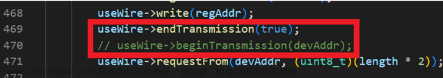
程序卡在 I2Cdev.cpp 的函数
int8_t I2Cdev::readWords(uint8_t devAddr, uint8_t regAddr, uint8_t length, uint16_t *data, uint16_t timeout, void *wireObj)中的
 useWire->endTransmission();
 useWire->beginTransmission(devAddr);
解决方案就是注释掉第二行:
再上传:

问题解决
大概这个库有问题应该都和文章来源:https://www.toymoban.com/news/detail-675539.html
 useWire->endTransmission();
useWire->beginTransmission(devAddr);这两行有关(主观臆断)文章来源地址https://www.toymoban.com/news/detail-675539.html
到了这里,关于[Arduino ESP32] mpu6050使用笔记(含dmp)的文章就介绍完了。如果您还想了解更多内容,请在右上角搜索TOY模板网以前的文章或继续浏览下面的相关文章,希望大家以后多多支持TOY模板网!